
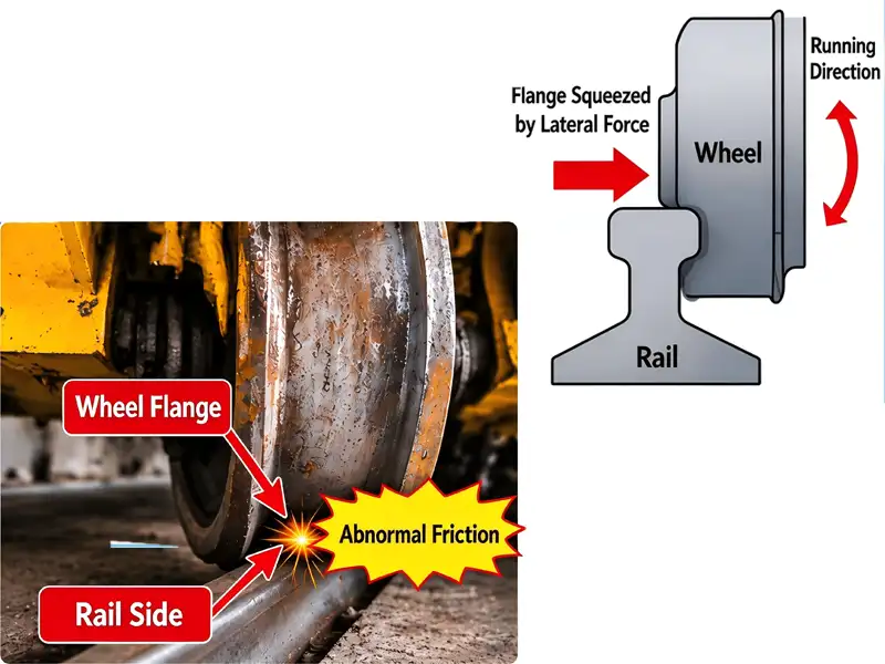
The rail gouging may appear to be a “clash” between the wheel and the rail, but the root cause does not necessarily lie with the wheel itself. Wheel flange rubbing is typically not caused by a defect in the wheel itself, but rather by deviations in track straightness and gauge, misalignment of the wheel, asynchronous drive between the two sides, or deformation of the bridge structure—all of which cause the wheel’s rolling direction to deviate from the track’s direction. As a result, the wheel flange continuously presses against the side of the rail and generates relative slippage, leading to wheel flange wear and crane rail wear. Effective repairs require first measuring the geometric parameters of the track and wheels, then verifying the condition of the drive system and structure, and making adjustments once the cause has been identified; simply replacing the wheels often leads to a recurrence of the problem.
How Wheel Flange Rubbing Develops
Under normal operating conditions, the wheel tread rolls along the top surface of the rail, and the flange maintains the clearance specified by design relative to the rail’s side surface.
Wheel flange rubbing occurs when the direction of wheel travel does not align with the direction of the track, or when the entire crane experiences lateral deviation during operation. In this situation, the wheel flange presses against the side of the rail: while the wheel continues to roll forward, the flange is continuously constrained by the side of the rail, causing relative slippage between the two and resulting in flange-to-rail friction. Under load, this contact relationship is referred to as flange-to-rail contact.
In short: the wheel wants to move in one direction, but the rail guides it in another; this constant conflict causes wheel flange wear on the wheel flange and crane rail wear on the side of the rail head.
If left unaddressed, wheel flange rubbing will continue to worsen, accompanied by abnormal noise, vibration, wheel flange wear, and damage to the side of the rail; in severe cases, it may also compromise the reliability of track fastenings and the operational safety of the equipment. When noticeable abnormal vibrations, severe wear, or signs of wheel derailment occur, relevant operations should be stopped immediately, and a professional inspection should be organized.
Typical Symptoms of Crane Wheel Flange Rubbing
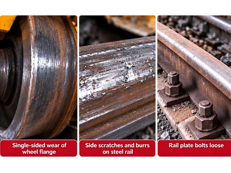
- Continuous metallic squeal caused by flange-to-rail friction
- A shiny wear band appears on the inner side of the wheel flange, with wear particularly noticeable on one side;
- Continuous scratches or burrs appear on the side of the rail;
- Abnormal vibrations occur during operation;
- Signs of loosening appear in track fasteners (clamps, bolts, etc.);
- In severe cases, the wheels may tend to climb the rails.
Five Common Causes
Rail Straightness Deviation or Change of Position
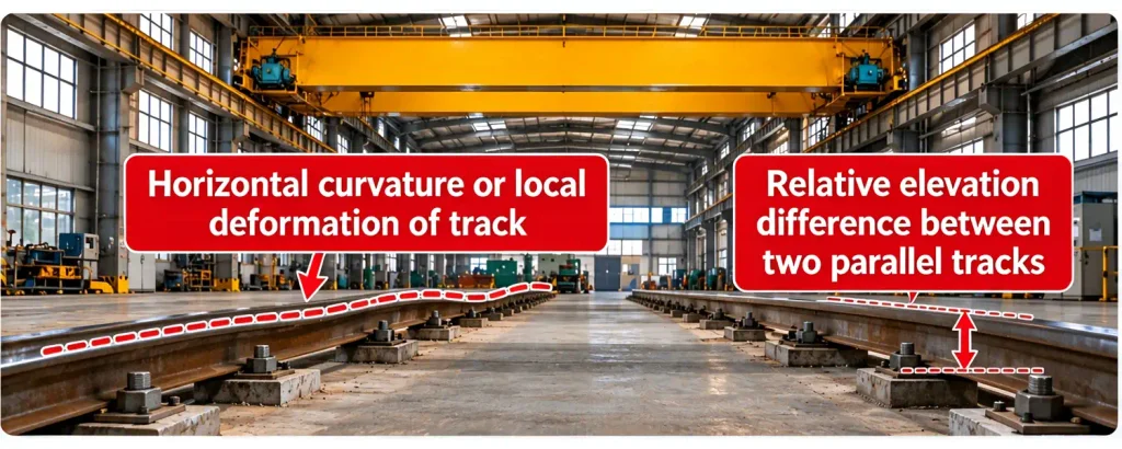
If deviations occur during track installation, or if the track is affected by factors such as deformation of the track-supporting beams, foundation settlement, or loosening of fasteners during long-term use, this may result in changes to the track’s straightness, gauge, or relative elevation on either side. These issues may cause abnormal lateral contact between the wheels and the rails. If rail gouging consistently occurs on the same section of track, the condition of that section should be inspected first.
Key Inspection Points:
- Do the dimensions meet design requirements?
- Is there any deviation in the straightness of the track?
- Are the relative elevations of the tracks on both sides within specifications?
- Are the track clamps and bolts loose?
- Are there any signs of deformation or settlement in the track-supporting beams?
Rails are the foundation of crane operation, and the quality of crane rail installation determines the operational baseline for the entire machine. Glory Rail recommends simultaneously recording variations in track gauge along the line and height differences at rail joints during the rail acceptance phase to preserve baseline data for subsequent fault diagnosis.
Wheel Mounting Skew
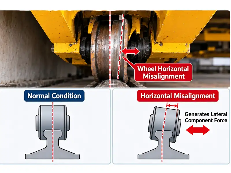
A wheel that rotate freely is not mean that they are installed correctly. Horizontal or vertical misalignment of the wheels, or geometric relationships between wheels in the same set that exceed the allowable limits, will all affect the crane’s ability to travel in a straight line.
For example, horizontal misalignment of a wheel will cause its rolling direction to deviate from the track direction, generating a lateral component of force during operation; abnormalities in wheel position, wheelbase, or diagonal relationships may also cause the entire machine to veer off course.
Such issues should not be assessed solely by visual inspection. Instead, parameters such as wheel installation deviations, wheelbase, and diagonal relationships should be measured in accordance with the equipment’s structure and maintenance procedures, and then verified against the equipment’s technical documentation and applicable standards. Permissible tolerances vary by machine model, so a one-size-fits-all approach should not be applied.
Misalignment during wheel installation is the most direct human-caused factor leading to wheel flange wear, and it is also a common cause of recurrence after wheel replacement.
Unsynchronised Dual Drives
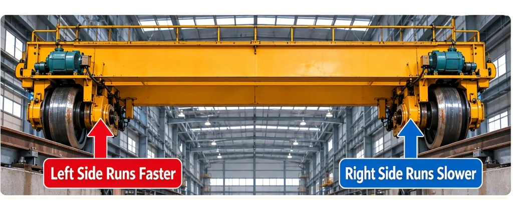
For a large crane travel mechanism driven independently on both sides, if there is a discrepancy in the actual travel speed or output status between the two sides, one end of the crane may run ahead while the other lags behind. When the travel conditions at both ends of the bridge are inconsistent, and since the wheels are constrained by the rails, the wheel flanges will continuously press against the sides of the rails.
This flange-to-rail contact can rapidly deteriorate into wheel flange rubbing. Possible causes include: inconsistencies in the condition of the motors, brakes, or transmission mechanisms on both sides; abnormalities in the gearbox or coupler; differences in wheel diameter and wear; or deviations in the inverter parameters, feedback signals, or synchronous control.
Therefore, when a large vehicle with separate drive systems experiences rail gouging, it is necessary not only to inspect the mechanical components but also to verify the status of the drive, braking, and synchronization controls on both sides in conjunction with the equipment’s control system.
Bridge or End Carriage Deformation
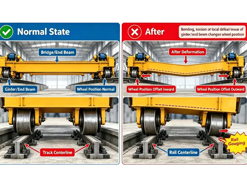
The bridge and end beams determine the critical geometric relationships of the entire crane. If the structure becomes deformed, or if cutting and welding during maintenance or modifications alter the structural configuration, this may affect the wheel mounting positions.
If rail biting occurs after maintenance, component replacement, or modification, it is especially important to verify the relevant geometric dimensions. When structural deformation is suspected, targeted measurements and technical assessments should be conducted.
Do not arbitrarily heat, cut, or weld the bridge girder to eliminate rail biting, nor should you repeatedly adjust the wheels without measurement data to support the adjustments. If structural issues have not been thoroughly investigated, adjusting the wheels may simply shift the deviation from one location to another.
Operating practice aggravating an existing defect
Frequent sudden starts and stops may increase shock and wear on the running gear. If the equipment already has track misalignment, wheel misalignment, or drive asynchrony, such operations will accelerate the deterioration of wheel flange rubbing.
However, rail gouging should not be attributed solely to operator error. While operating habits are a contributing factor, they cannot replace inspections of the equipment itself. The proper approach is to first inspect the rails, wheels, bridge structure, and drive system, and then analyze the extent to which operational factors contribute to the issue by reviewing operational records.
Five-Step Field Diagnosis
Step 1 — Record where and in which direction
Observe in which section and in which direction of travel friction occurs. If wheel flange rubbing consistently occurs on the same section of track, inspect that section first; if the entire unit shows a noticeable deviation during operation, further inspect the wheel alignment, the bogie, and the drive system. These observations are used only to narrow down the scope of the investigation and should not be taken as definitive evidence.
Step 2 — Inspect flange and rail wear marks
Check whether wheel flange wear is one-sided, whether the rail sides shows continuous scratches or burrs , and whether the rail fasteners have loosened. Record the locations of wear and analyze them in relation to the operating section. Wear marks are important clues, but should not be used as the sole basis for determining liability.
Step 3 — Measure rail and wheel geometry
Based on the equipment’s structure, applicable standards, and maintenance requirements, inspect parameters such as track gauge, track straightness, relative elevations on both sides, wheel mounting deviation, wheelbase, and diagonal measurements, and compare them with the equipment’s technical specifications. Tolerances governing flange-to-rail contact geometry are defined in ISO 12488-1 / GB/T 10183.1. Measure along the full runway, not at isolated points.
Step 4 — Check drive, brake and control system
For large vehicle systems with separate drives, inspect the motors, gearboxes, couplings, brakes, and control systems on both sides; if a variable-frequency drive is used, also verify the parameters, fault logs, and synchronous control status. Abnormal vibration accompanied by noise is a strong indicator of flange-to-rail friction caused by drive mismatch.
Step 5 — Adjust only after the cause is confirmed
Do not repeatedly adjust the wheels, arbitrarily change parameters, or directly replace parts without measurement data. After adjustments are complete, retest in accordance with maintenance procedures and conduct a controlled test run to confirm that wheel flange rubbing has been resolved.
Why Does Rail Biting Recur Even After Replacing the Wheels?
Although the wheels may be the components that sustain direct damage, they are not necessarily the initial source of the failure. If the track is not straight, the new wheels will still have to run along the misaligned track; if the drive on both sides is out of sync, the new wheels will be unable to automatically synchronize the two ends; and if the bridge geometry is abnormal, the wheels may still be in an incorrect installation position.
Therefore, if the track, installation dimensions, and drive system are not inspected at the same time as the wheels are replaced, track gouging is highly likely to recur. Effective maintenance involves not only replacing worn parts but also identifying and eliminating the root causes of the wear.
Component Matching and Selection
When inspecting and repairing crane rail wear and flange damage, the compatibility of replacement parts also affects the results:
Rail Type and Wheel Tread Matching
The rail head width, tread width, and flange height of QU Series crane rails must match as specified in the drawings; using wheels designed for different rail types will alter the flange clearance.
Clamping Force and Corrosion Resistance Rating of Rail Fasteners
Loose clamping plates will directly alter the track gauge; fasteners should be selected based on the rail type and operating conditions.
Wheel Material and Heat Treatment
Insufficient flange hardness accelerates wheel flange wear, while excessive hardness may damage the rail side face.
Consistency of Replacement Parts
Differences in wheel diameter on the same piece of equipment should be kept within the permissible range; otherwise, it will cause the train to run off track.
Glory Rail provides selection charts for crane rails, hoist wheel sets, rail clamps and bolt fasteners, hooks, drums, and pulleys to assist with on-site replacement based on rail type and drawing number.
Conclusion and Contact
When addressing rail-biting issues with overhead cranes, one should not focus solely on the wheels. First, determine whether the fault is related to a specific operating section; then measure the geometric parameters of the rails and wheels; and finally, inspect the girder, drive, and braking systems. Adjustments should only be made after the cause has been confirmed to avoid repeated repairs.
If severe flange damage, loose rail fasteners, abnormal vibrations, or signs of wheel derailment have occurred, operations must be stopped immediately, and professional personnel must be organized to conduct inspections and repairs. Operating the equipment while it is faulty is strictly prohibited.
If you are selecting or replacing crane rails, crane wheel sets, or rail fasteners, please contact Glory Rail to obtain rail profile comparison charts and technical specification sheets. Our engineering team can assist you in verifying the compatibility between rail profiles, wheel treads, and fasteners.
This article is intended to provide general information on mechanical knowledge and to facilitate discussions on on-site troubleshooting. Specific inspection items, allowable tolerances, and repair methods should be determined in accordance with the equipment manufacturer’s technical documentation, applicable standards, and approved maintenance plans.
Get In Touch
After submitting the form, your dedicated account manager will contact you immediately to provide full-process technical support from selection to installation.
Your Expert in Crane Rail Solutions
To help us provide a faster and more accurate tailored solution, please consider including:
1. Rail Specifications: Rail section type, profile, or standard, and your required unit length.
2. Order Quantity: Total quantity of rails, matching fasteners, or related equipment needed.
3. Material & Grade: Specific steel material requirements or performance grades.
4. Technical Files: Any custom technical requirements, drawings (CAD/PDF), or project specifications.
Don’t have all the details? No worries! Just leave us a message with what you know, and our experts will guide you through the process.