
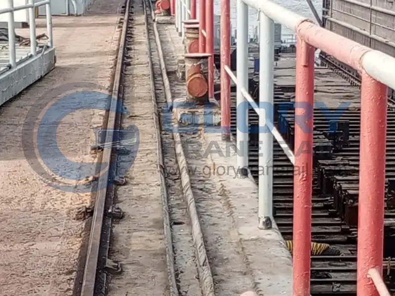
During shipbuilding and the operation of lifting equipment at large shipyards, rail systems must withstand significant crane wheel loads, dynamic loads, and forces generated by equipment startup and braking over extended periods. At the same time, corrosive factors such as salt spray, humidity, and the marine environment place higher demands on the protective performance of rails and associated steel structural components.
Therefore, a reliable Shipyard Crane Rail System requires not only the appropriate selection of rail types but also comprehensive consideration of factors such as rail end processing, fastening structures, foundation anchoring, elastic buffering, and anti-corrosion coating.
To meet the heavy-duty operational demands of shipyards, Glory Rail provides crane rails and related components, and offers customized rail cutting and surface corrosion protection treatments based on engineering drawings. Using DIN 536 A120 rails as a technical reference, this article introduces the key technical requirements for heavy-duty rail systems, installation methods for different fastening structures, and the corrosion protection processing procedures for steel structural components.
01. A120 Crane Rail: Profile Dimensions and Material Requirements
In heavy-duty shipyard track systems, the A120 is a large Type A crane rail with a rail base, as defined in the DIN 536 standard. Its larger rail head and rail base dimensions provide the necessary structural foundation for heavy-duty crane track systems.
The main cross-sectional parameters of the A120 crane rail are as follows:
| Technical Parameters | A120 Specifications |
|---|---|
| Standard | DIN 536 p1:1991-09 |
| Rail Height | 105mm |
| Head Width | 120mm |
| Foot Width | 220mm |
| Web Thickness | 72mm |
| Sectional Area | 127.4cm² |
| Theoretical Weight | 100.0kg/m |
| Material | U71Mn |
| Minimum Tensile Strength | Rm ≥ 880 MPa |
For heavy-duty applications such as shipyards, the selection of rails must be determined comprehensively, taking into account the single-wheel load of the crane, the frequency of equipment operation, the track support structure, and the foundation conditions. Track specifications and material strength are two technical parameters that must be verified separately; the load-bearing capacity of the entire track system cannot be determined solely based on the theoretical weight of 100 kg/m.
02. 45° Crane Rail End Cutting: Precision Processing for Rail Installation
Track end machining is a critical step in the manufacturing and installation preparation of heavy-haul rails. For track systems requiring specific joint configurations, the rail ends can be cut at a 45-degree angle in accordance with engineering drawings, ensuring that the geometry of adjacent rail ends matches the specified joint arrangement.
Compared to conventional 90° right-angle cuts, 45° bevel cuts can create different rail-end joint geometries and are suitable for track installation structures where engineering drawings explicitly require beveled joints.
For heavy-duty crane rails such as the A120, the following aspects require special attention during end machining:
Cutting Angle Control
Determine the 45°bevel angle and cutting direction based on the machining drawings to ensure that the machining direction of adjacent rail sections matches the joint design.
Dimensional Accuracy
Control the cutting position and end dimensions to ensure that the rail length and bevel position meet the drawing requirements, thereby reducing machining deviations between different rail sections.
Edge Finishing
Remove burrs, sharp edges, and irregularities created during the cutting process to prepare for subsequent installation and joint alignment.
Joint Compatibility
Check the end orientations and joint types of adjacent rail sections based on the rail joint design to ensure that machining dimensions match on-site installation requirements.
Glory Rail’s Crane Rail Cutting Capabilities
Glory Rail offers customized crane rail end cutting services based on customers’ drawings and dimensional specifications, including standard straight cuts and 45° bevel cuts.
For heavy-duty crane rails such as the A120, we place particular emphasis on controlling the cutting angle, rail end orientation, and end dimensions to ensure that the processed rails meet the specified joint configurations and on-site installation requirements.

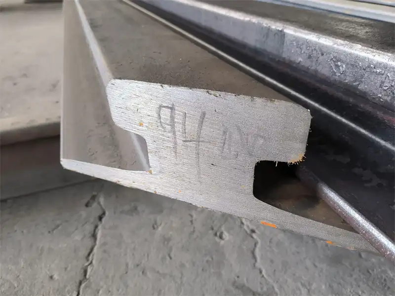
Technical Note: A 45° bevel cut is a custom machining requirement for this project and is not a standard machining procedure that must be performed on all DIN 536 A120 rails. The actual cutting angle, direction, and joint configuration shall be determined in accordance with the approved engineering drawings.
03. Crane Rail Fastening System: Two Installation Arrangements
In a Heavy-Duty Crane Rail Fastening System, the primary function of rail clamps is to constrain the position of the rails and transfer the associated forces to the steel base plates and the foundation structure.
Depending on the design of the steel base plates and the actual installation conditions, two different connection methods may be considered:
- Forged Bolted Rail Plates / Bolted Rail Clips.
- Welded Rail Clips.
These two designs represent different installation solutions and must be selected based on the specific rail support structure and engineering design; they should not be regarded as components that must be used simultaneously within the same fastening system.
Option A: Forged Bolted Rail Plates
Forged steel bolt-type clips are mechanically fastened to the designated load-bearing steel structure to clamp the rail foot and constrain its position.
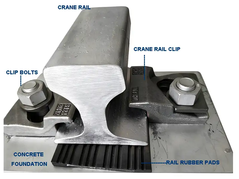
A typical installation consists of the following components:
| Installation Component | Function |
|---|---|
| A120 crane rail; | Installed on the rail support surface |
| Rubber rail pad | Installed between the rail and the support surface in accordance with design requirements |
| Steel soleplates | Provides mounting supports for rails and fastening components |
| Forged rail plates | Positioned on both sides of the rail base, they fit against the rail base. |
| Grade 8.8 bolts & nuts | Secure the clamping plate to the designated load-bearing steel member |
| Anchor bolt system | Secure the steel shims to the concrete foundation |
| Concrete foundation | Provides overall structural support |
The primary technical considerations for this structure include:
- The contact geometry between the clamping plate and the bottom of the A120 rail.
- The bolt hole locations and installation orientation.
- The spacing of the clamping plates and fastening requirements.
- The compatibility of the steel shims with the bolted connection structure.
- Hot-dip galvanizing treatment and thread mating requirements.
The main components specified in the original technical requirements include:
| Components | Specifications |
|---|---|
| Rail Plate | Forged Steel |
| Surface Treatment | Hot-Dip Galvanized |
| Bolts and Nuts | Grade 8.8 |
Option B: Welded Rail Clips
For heavy-duty track systems with steel base plates, welded rail clips can also be used.
Unlike bolted clamps, welded rail clips are directly welded to the steel base plate and secure the track in place by engaging the working end of the clip with the rail web.
A typical installation configuration is as follows:
| Installation Component | Function |
|---|---|
| A120 crane rail; | Installed on the rail support surface |
| Rubber rail pad | Installed between the rail and the support surface in accordance with design requirements |
| Welded rail clips | Positioned on both sides of the rail base, they fit together with the rail base |
| Welding Connection | Secure the rail clamp to the steel backing plate |
| Steel soleplates | Provides mounting supports for rails and fastening components |
| Anchor bolt system | Secure the steel shims to the concrete foundation |
| Concrete foundation | Provides overall structural support |
In this structure, the welded rail clamp forms a fixed connection with the steel backing plate via a weld. Lateral forces acting on the rail are transmitted by the rail clamp to the welded joint, and then to the steel backing plate and its foundation anchorage structure.
Compared to bolted installations, the design of welded structures focuses more on:
- The contact configuration between the rail clamp and the rail foot.
- The welding location between the rail clamp and the steel base plate.
- The dimensions, configuration, and quality of the welds.
- The spacing of the rail clamps and lateral restraint requirements.
- Corrosion protection and overall coating after welding is complete.
For heavy-rail systems that must withstand significant lateral forces, welded rail clamps can be considered a viable fastening option; however, the final selection must still be determined based on track load calculations, the steel base plate structure, and on-site installation conditions.
Bolted vs. Welded Crane Rail Clips: Key Differences
| Comparison | Forged Bolted Rail Plates | Welded Rail Clips |
|---|---|---|
| Connection | Bolted Connection | Welded Connection |
| Main Components | Forged plates, bolts and nuts | Welded clips and soleplate |
| Fixing Position | Designated supporting steelwork | Steel soleplate |
| Installation Focus | Bolt arrangement and clamping geometry | Weld details and clip positioning |
| Key Design Factors | Mechanical connection and clamping arrangement | Lateral restraint and weld connection |
For the A120 heavy rail system at the shipyard, if a steel shim structure is used, welded rail clamps can be considered one of the preferred options; particular attention should be paid to the lateral forces generated during rail operation and the on-site installation conditions.
04. Crane Rail Rubber Pads and Anchor Bolt System
In addition to rails and rail clamps, rubber pads and anchor bolts are also important components of the Heavy-Duty Crane Rail System.
4.1 Crane Rail Rubber Pads: Vibration Absorption and Wear Resistance
During crane operation, the rail system is subject to dynamic wheel loads and operational vibrations. Properly installing crane rail rubber pads allows the deformation characteristics of the elastic material to absorb some of the operational vibrations, thereby mitigating dynamic impacts between the rails and the supporting structure.
| Technical Parameters | Requiremrnts |
|---|---|
| Material | Wear-Resistant Synthetic Elastomer |
| Hardness | 75 Shore A |
| Hardness Testing Reference | ISO 48-4:2018, where specified |
Among these, Shore A is a hardness testing scale suitable for rubber materials within the standard hardness range.
Hardness data is not the sole criterion for selecting rubber pads. In practical applications, evaluation must also take into account factors such as the thickness of the rubber pad, its compression characteristics, dynamic stiffness, and the long-term operating environment.
4.2 M24 Crane Rail Anchor Bolt System
The anchoring system secures the steel base plates and rail support structure to the concrete foundation and is a critical component of the crane rail anchor bolt system.
The main anchoring components are configured as follows:
| Components | Material & Specifications |
|---|---|
| Anchor Bolt | High Tensile Steel, Grade 8.8, M24 |
| Fixing Nut | Mild Steel Hex Nut, M24 |
| Flat Washer | Mild Steel Washer, M24 |
| Surface Treatment | Hot-Dip Galvanized |
Grade 8.8 is a mechanical performance grade for bolts; its mechanical properties may be specified and verified in accordance with ISO 898-1:2013. For M24 hot-dip galvanized threaded fasteners, the relevant galvanizing requirements may be specified in accordance with ISO 10684:2004.
In actual engineering design, the specifications, quantity, spacing, and embedment depth of anchor bolts must be determined comprehensively, taking into account the crane’s wheel load, the forces generated during starting and braking, the arrangement of steel shims, and the conditions of the concrete foundation.
Technical Note: M24 refers to the nominal diameter in specific technical specifications; the embedment depth of anchor bolts cannot be directly derived based solely on the rail type or weight per meter. The mechanical performance matching between bolts and nuts should also be specified in the final procurement specifications.
05. Crane Rail Corrosion Protection: Surface Preparation and Protective Coating
In shipyards and marine environments, steel rail support structures and associated components are exposed to environmental factors such as salt fog, moisture, and corrosive deposits.
Therefore, crane rail corrosion protection should not focus solely on the color of the final coating; it must also take a comprehensive approach that considers surface pretreatment, coating systems, application control, and final coating inspection.
5.1 Sa 2½ Abrasive Blast Cleaning
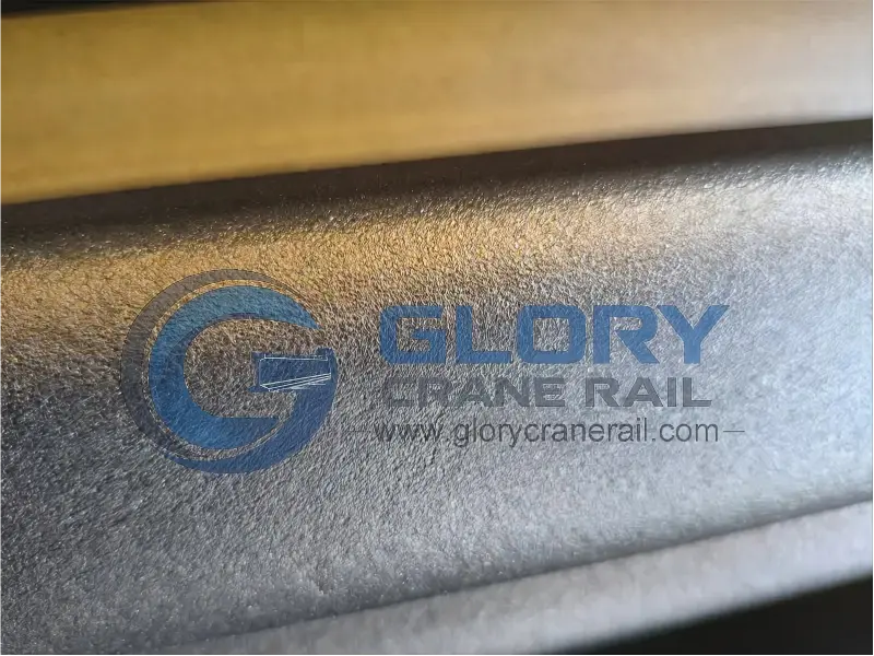
Prior to applying the anti-corrosion coating, steel shims and specified steel components must undergo sandblasting to meet the corresponding surface cleanliness requirements.
Among these, Sa 2½ abrasive blast cleaning corresponds to the “Very Thorough Blast-Cleaning” grade, as technically defined in ISO 8501-1:2007.
This grade requires that the steel surface be thoroughly blast-cleaned to achieve the cleanliness level specified by the standard, with no visible scale, rust, old coatings, or other contaminants remaining.
Proper blast cleaning pretreatment helps remove surface contaminants and provides a surface condition that meets the requirements for subsequent anti-corrosion coating application.
During the blast cleaning process, special attention should be paid to the following:
- Surface Cleaning: Remove visible grease, dirt, and loose rust before blast cleaning.
- Blast Cleaning: Complete surface cleaning of the steel as required to achieve the Sa 2½ grade.
- Dust Removal: Remove any abrasive residue and loose dust remaining after sandblasting.
- Surface Inspection: Inspect surface cleanliness prior to painting, and verify surface roughness and application environmental conditions in accordance with the coating specifications.
Glory Rail’s Surface Preparation Capabilities
Glory Rail provides sandblasting services for specified crane track support components (including steel base plates) in accordance with project specifications. Through standardized sandblasting, rust, scale, and adhering contaminants are removed from the surfaces of steel structural components, preparing them for subsequent coating processes.
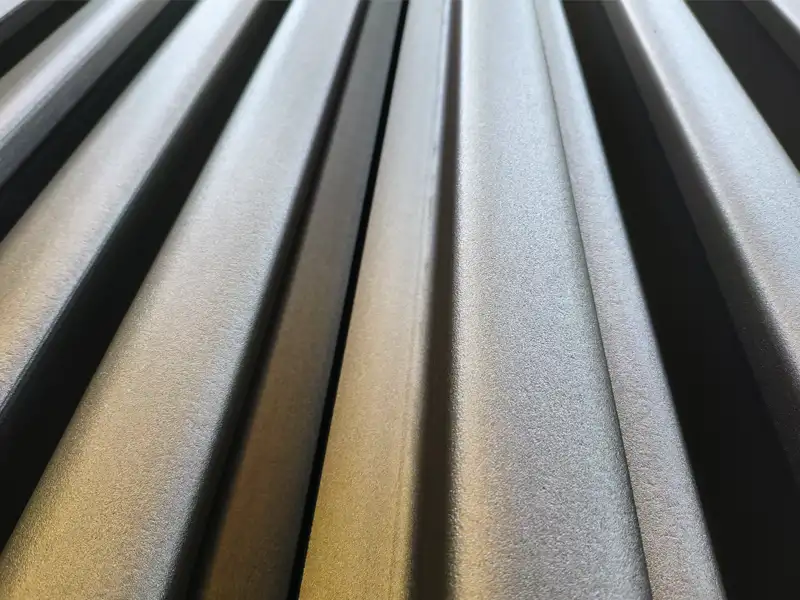

5.2 Jotun Multi-Layer Protective Coating System
After sandblasting pretreatment is complete, a multi-coat protective system consisting of a primer, intermediate coat, and topcoat can be applied based on the project’s corrosion environment and technical requirements.
For specific steel structural components, such as steel base plates, the following is a specific Jotun coating configuration:
| Coating Process | Jotun Product | Dry Film Thickness | Note |
|---|---|---|---|
| Surface Preparation | Sa 2½ | —- | —- |
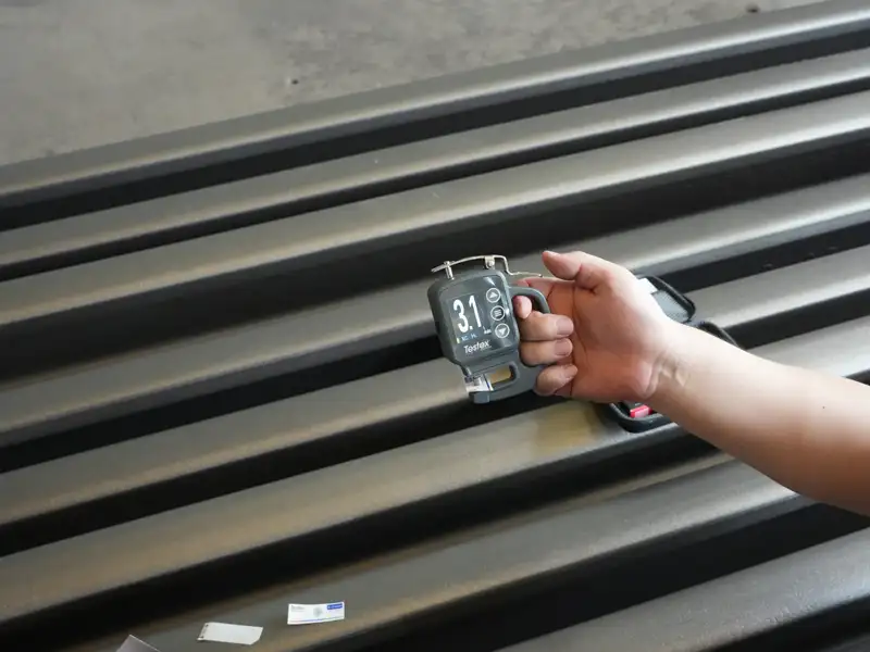
| Primer | Barrier 8o Grey | 65 µm | The primer serves as the first layer of the protective system, providing a foundation for subsequent coats. 65 µm is the specified application requirement. |
| Intermediate Coat | Jotamastic 87 Buff | 200 µm | The intermediate coat is used to increase the overall coating thickness and form an additional protective barrier. |
| Topcoat | Jotamastic 87 Orange | 150 µm | The topcoat serves as the final layer, completing the specified multi-layer protective system and meeting the corresponding aesthetic requirements. |
| Total DFT | Three-Coat System | 415 µm | —- |
In actual spray coating operations, it is also necessary to follow the technical data sheets (TDS) for the corresponding Jotun products to control the paint mix ratio, application temperature, humidity, recoat intervals, and final dry film thickness.
Glory Rail’s Anti-Corrosion Processing Capabilities
For rail support components used in shipyards and outdoor environments, Glory Rail offers customized crane rail corrosion protection services tailored to each project’s specific requirements.
Related processing services include:
- Sandblasting pretreatment according to specified grades.
- Application of primer, intermediate coat, and topcoat as required.
- Control of coating thickness in accordance with project DFT requirements.
- Coordination of surface treatment requirements for steel base plates and various fastening components.
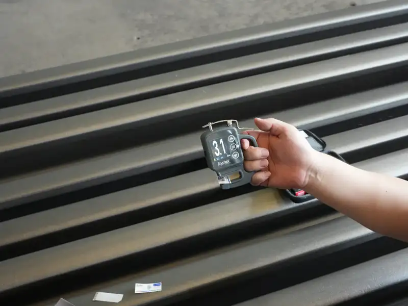
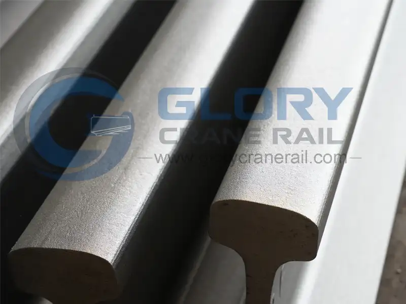
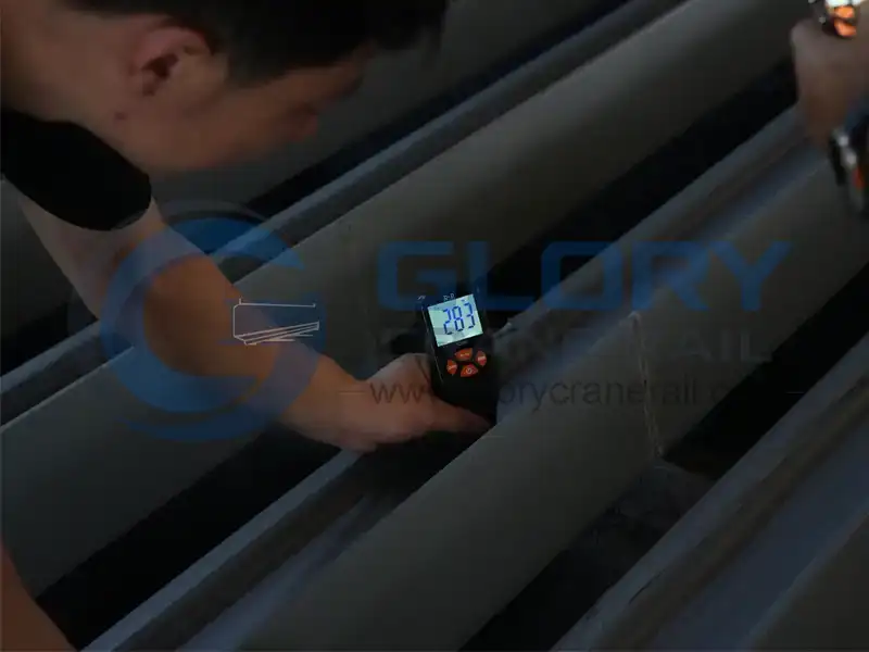
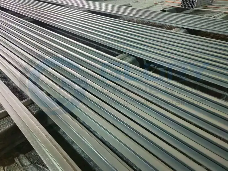
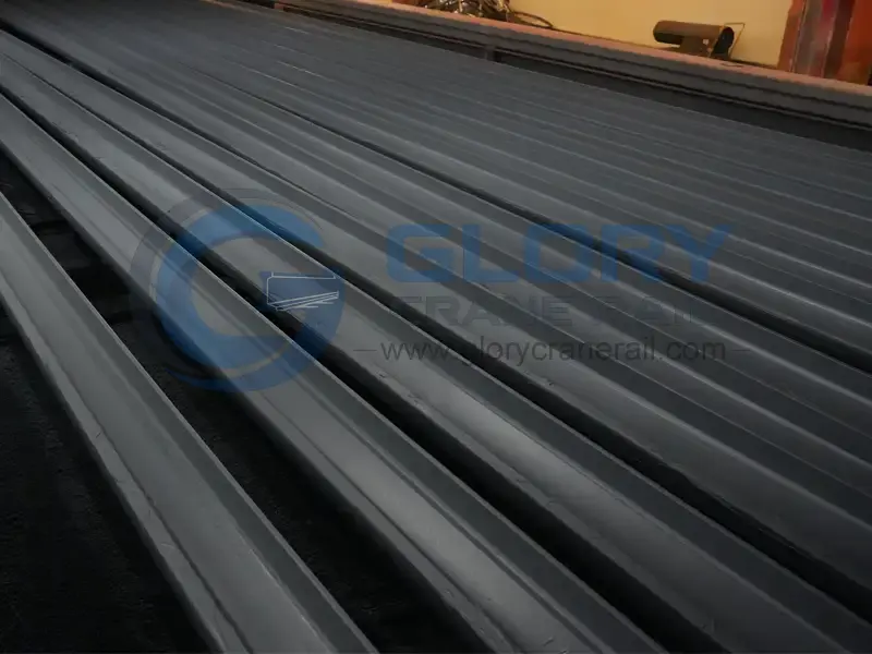
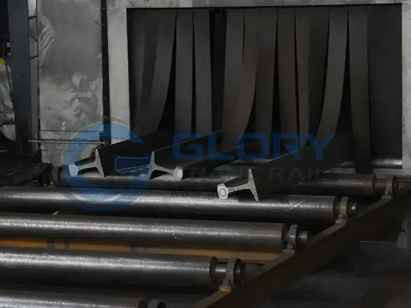
Through standardized surface treatment and coating application, appropriate corrosion protection can be provided for steel base plates and other specified steel structural components.
Technical Note: The aforementioned 415-micrometer coating system is intended for specified steel structural components, such as steel shims, that require coating. Anchor bolt assemblies are specified as hot-dip galvanized in the original design requirements; this should be confirmed separately from the multi-layer coating requirements for steel shims, and the 415-micrometer coating should not be applied to threaded fasteners by default.
06. Complete Crane Rail System: Integrated Component Supply
In heavy-duty rail projects at shipyards, the coordination of rails, fasteners, anchoring systems, and anti-corrosion treatments must be integrated around a single installation structure.
Depending on the scope of the project, a complete crane rail system may include the following supporting components:
Glory Rail can coordinate the supply of products such as rails, rail clamps, rubber pads, anchor bolts, and steel shims according to project requirements, and handle rail cutting and anti-corrosion coating requirements for specified steel structural components based on fabrication drawings.

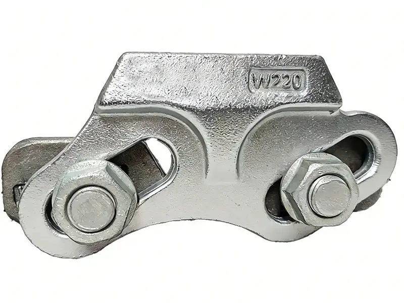


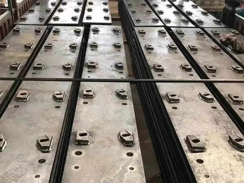
In addition to product manufacturing and supply, it is necessary to uniformly verify the dimensional compatibility between the rails and fastening structures, as well as material requirements, fabrication drawings, and surface treatment specifications.
Conclusion: Engineering Support for Shipyard Crane Rail Systems
The heavy-duty crane rail system for shipyards involves multiple interrelated engineering aspects. From the cross-sectional specifications of A120 rails and the material properties of U71Mn, to the 45° end bevel, the installation structures of various types of rail clamps, and on to rubber pads, anchoring components, and multi-layer anti-corrosion coatings—each aspect must be appropriately configured based on actual installation conditions and the operating environment.
For projects requiring custom fabrication and supporting components, Glory Rail can provide crane rails, rail fasteners, and related accessories. We also offer rail cutting and anti-corrosion surface treatment services based on engineering drawings, helping customers ensure compatibility between rail products and installation systems.
Are you planning a shipyard crane rail project?
Please contact Glory Rail and provide rail specifications, crane wheel load, installation drawings, and on-site environmental requirements to further discuss suitable rail processing, fastening structures, and anti-corrosion configuration solutions.
Get In Touch
After submitting the form, your dedicated account manager will contact you immediately to provide full-process technical support from selection to installation.
Your Expert in Crane Rail Solutions
To help us provide a faster and more accurate tailored solution, please consider including:
1. Rail Specifications: Rail section type, profile, or standard, and your required unit length.
2. Order Quantity: Total quantity of rails, matching fasteners, or related equipment needed.
3. Material & Grade: Specific steel material requirements or performance grades.
4. Technical Files: Any custom technical requirements, drawings (CAD/PDF), or project specifications.
Don’t have all the details? No worries! Just leave us a message with what you know, and our experts will guide you through the process.